
Page 60 - CNC Robotics
P. 60
Chapter 2 / Electroni cs
APPLICAnON NOTE
The output waveformsfor this sequenceare shown thesequencegenerateddependson thestate of the
in figure 1O. translator when full step mode is selected (the
Note that two othersignal s,TNR1 and INH2 are ge- HAlFI FULLinput brought low).
nerated in this sequence.The purpose of these si-
gnals is explained a little further on. If fullstep mode is selectedwhenthe translator is at
any odd -numbered state we get the two-phase-on
The full step modes are both obtained by skipping full step sequence shown in figure 11.
alternate states in the eight-step sequence. What
happensis that thestep clock bypassesthe first sta- By contrast ,one-phase-on full step mode is obtai-
ge of the 3-bil counterin the translator.The least si- ned by selecting full step mode 'When the translator
gnificant bit 01this counter is not affectedtherefore is at an even-numberedstate (figure 12).
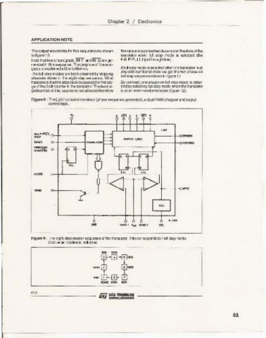
Figure 8 : The L297 containstranslator (phase sequence generator),a dual PWMchopper andoutput
control logic.
.II INHl 8 C INHl 0
u.,
H..lF /FUll o~~-----1---l
STEP 1---- /-0.......
OUTPUT lOGIC
RESU o-+-----~ TANtSU.11JR \--- - -+-oCOll_
DOI..ten ...
(CWK:tW) o-+--ID •
..... +-- -+-0,,"<
""" sus 1 Yr.t sus 1
Figure 9 : The eight step master sequenceof the translator.This corresponds to half step mode.
' .....
Clockwise rotation is indicated.
L 1001 1000
[J
0001 1 fa ODD
OKll I B 7
tfCIoIE 0100 0110
6/18
51