Page 59 - CNC Robotics
P. 59

GNG Robotics


                                                                              APPLICATION NOT E

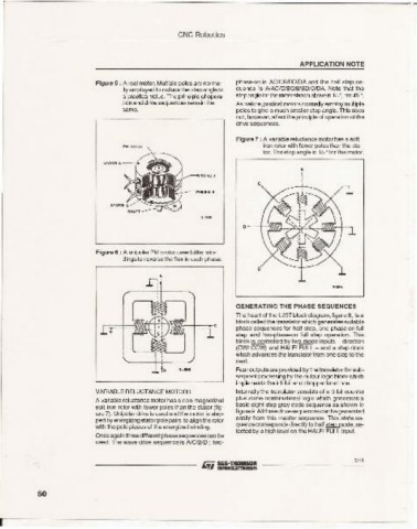
                          Figure 5 : A real motor. Multiple poles are norma-  phase-on is AClCBlBDIDA and the half step se-
                                lly employed to reduce the step angleto  quence is N AC/C/BCI8JBO/OtDA. Note that the
                                a practicalvalue. The principle of opera-  stepangleforthe motorshownaboveis 15°, not45 0 .
                                tion and drive sequences remain the  As before. pratical motors normally employ multiple
                                same .                        po les to give a much smaller step angle. This do es
                                                              not , however, affectth e prlrcole of operation of the
                                                              drive sequences.

                                                              Figure 7 : A variable reluctance motor has a soft
                                                                     iron rotor with fewer poresthan th e sta-
                                                                    tor. The step angle is 15 ° for this motor.
                                                                              •

                                                                   c


                                                               •


                          Figure 6 : A unipolar PM rrotoruses Milar win-
                                dings to reverse the flux in each phase.
                                          •
                                      D ,


                                                              GENERATI NG THE PHASE SEQUENCES
                                                              The heart of the l297 bloc k diagram, figure 8, is a
                                                              block called the translator whic h generatessuilable
                                                              phase sequences for half step, one-phase-on fuU
                                                             step and two-phase-on full step operation. This
                                                             block is controlled by two mode inputs - direction
                                                              ICWI CCW) and HALFI FULL - and a step clock
                                                             which advances the translator from one step to the
                                                              next.
                                                              Four out puts are provded by the translator for sub-
                                                             sequent processing by the outp ut logic block which
                                                              implements the inhibit and chopper functions.
                          VARIABLE RELUCTANCE MOTORS          Internally th e translator con sists of a 3- bit counter
                          A variable reluctance motor has a non-magnetized  plus so me co mbinational logic which generates a
                                                             basic eight-step gray code sequence as shown in
                          soft iron rotor with fewer po les than the stator (fig-
                          ure 7). Unipolar driveis usedand the motor is step-  figure9.Anthree drive sequencescan be generated
                                                             easily from this master sequence. This sta te se -
                          ped by energizing statorpolepairs to alignthe rotor
                          with the polepieces of the energizedwinding.  qu ence correspondsdirectty to half ~mode. se-
                                                             lectedby a high level on the HALFI FULL irout.
                          Onceagainthreedifferentphasesequercesca n be
                          used. The wave drive sequence is NCIBID ; two-
                                                                                            51'8


           50


 r-    -    -    -    -    -    -    -    -    -    -    -    -    -    -    -    -    -    -    -
   54   55   56   57   58   59   60   61   62   63   64