Page 63 - CNC Robotics
P. 63

CNC Robotics


                                                                              APPLICATION NOTE

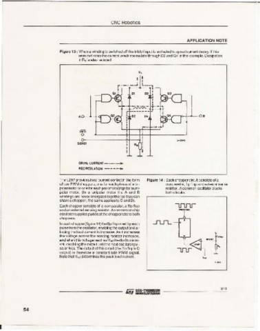
                          Figure 13 : When a winding is switched off the inhibit input is activated to speed current decay. If this
                                 were not done the current would recirculate through 02 and 0 4 in this example. Dissipation
                                 in Rs is also reduced.

                                                          v•
                                                           •   ,
                                                           ,
                                                           L


                                                     r ------ -
                                                     ,
                                                     , 0 , ,  02  D.   , -.>-+---4-- 06
                                                     , I
                                  INHi
                                                           i
                                                           0
                                                                          s-s...
                                 SENS'                  R.  0
                                                           0
                                                           t
                                 DRIVE CURRENT_ .  ..
                                 RECIRCUL ATION --- --.

                          The L297 provides load curre nt control in th e form  Figur e 14 : Each choppercircuil consists of a
                          of two PWM choppers,one for each phase of a bi-  comparator,flip flop and external sense
                          polarmatoror oneforeachpairef windingsforauni-  resistor. Acommon oscillatorclocks
                          polar motor. (In a unipolar motor the A and 8  both circuits.
                          wirdings are neverenergizedtogether so thaycan
                          share a chopper ; the same applies to Cand O).
                          Each chopper consists of a comparator, a flip flop
                         and an extemalsensingresistor. Acomrron on chip
                         oscillatorsuppliespulsesat the chopperrateto both
                         choppers.
                          Ineachchopper(figure 1 4) the tl~ flop isset by each
                          pulsefrom theoscillator, enablingtheoutputand al-
                          lowing the load current to increase. As it increases
                         the voltage across the sensing resistor increases,               ' ",,0
                          and when this voltage reachesVref theflip flop is re-       '"''
                          set, disablingthe output untilthe next osciilator pul-
                          se arrives.Theoutput of thiscircuit (the flip flop's Q          '.
                         output) is therefore a constant rate PWM signal.
                          Note that Vref determines the peak load current.          ....


                                                                                            9/18


           54


 r~~~~~~~~~~~~~~~~~~~~~~~~-
   58   59   60   61   62   63   64   65   66   67   68