
Page 67 - CNC Robotics
P. 67
CNC Robotics
APPLICATION NOTE
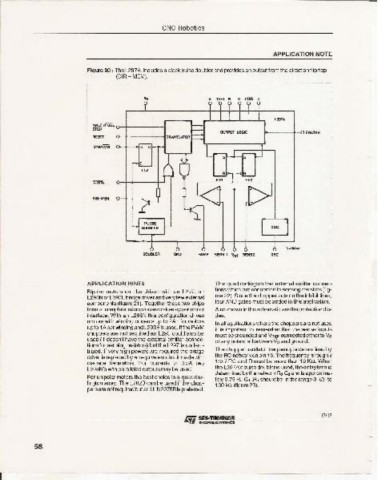
Figure 20 : The L297A, includes a clock pulse doublerand provides an outputtrom the direction flipflop
(DIR-MEM).
A lNHl B C iNH1 D
L197A
~:i~'f'urL o-+-----~
OUTPUT LOGIC I----t-~ ENABlE
RESET o-+-----~tRANSLATOA
CCWICCW o •
c
DtR-MEM
000..... ONO HOME SENS 1 Ynt SENS2 OSC
APPLI CATION HINTS This quad darlington has external emitter conneo -
Bipolar motors can be driven with an l297, an tions which are connected to sensing resistors (fig-
L29aN or L293Ebridge driver and veryfew external ure 22). Since the chopper acts on the inhibit lines,
compon ents (figure 21). Together these two chips four AND gates must be added in this application.
form a complete microprocessor-to-steppe r motor Also shown in the schemat ic are the protection dio-
interface. With an L298N this config uration drives des.
motors with winding currents up to 2A ; for motors
In allapplications where the choppers are not used
up to 1A per winding and L293E is used . If the PWM it is important to remember that the sense inputs
choppers are not required an L293 cou ld also be must be grounded and VREF connectedeitherto ve
used (it doesn't have the external emitter connec -
or any potential bet ween Vs and ground.
tions for sensing resistors) but the L297 is underu-
tilized. If very high powers are req uired the bridge The chopperoscillato r frequency is determined by
the RC network on pin 16.The frequencyisroughly
driver is replaced by an equivalent circuit made with
discrete transistors. For currents to 3.5A two 1/0.7 RC and R must be more than 10 Kn. When
L298N's with paralleled outputs may be used. the L297A'spulsedoubleris used, thedelaytime is
dete rmined by the network R:J CJ and is approxima-
For unipolar motors the best choice is a quad dar- telyO.75 Rd w .R::1 should be in the range 3 kn to
lington array. The L702B can be used if the chop-
100 kil (figure 23).
persare not required but an ULN2075B is preferred .
13118
58
I ~~~~~~~~~~~~~~~~~~~~~~~~~~-