
Page 64 - CNC Robotics
P. 64
Chapter 2 / Electronics
APPLICATION NOTE
PHASE CHOPPIN G AND INHIBIT age on the winding is low (Vcsset 01 + VD3) (figure
CHOPPING 16).
The chopper can act on either the phase lines Why is Bpulled high, why push A low ? The reason
(ABCD)oronthe inhibit lines INHl and INH2.An in- isto avoid the current decayingthrough Rs. Since
put named CONTROL decides which. Inhibitchop- the current recirculatesinthe upperhalf of the brid-
ping is usedfor unipolar motors but you can choose ge, current only flows in the sensing resistor when
between phasechopping andinhibitchoppinqforbi- the winding is driven. Less power is theretoredissi-
polar motors. The reasons for this choice are best pated in Rsand we can getawaywith a cheaper reo
explained with another example. sistor.
This explain why phase chopping is not suitable for
First let's examine the situation when the phase li- unipolarmotors : when the A winding is driventhe
nes are chopped . chopperactsonthe Bwinding.Clearly,thisisno use
at all for a variablereluctance motor and would be
As before, we are driving a twophase bipolar motor slow and inefficient for a bifilar wound permanent
and A is high, B low (figure 15). Current therefore magnet motor.
flows through 01 , winding, 04 and Rs. When the The alternative is to tie the CONTROL input to
voltage across Rs reaches Vref the chopper brings ground so that the chopper acts on INH1 and INH2.
B high to switch off the winding. Looking at the same example,A is high and Blow.
The energy stored in the winding is dissipated by 01 and 04 are therefore conducting and current
currentrecirculatingth rough01 and 03. Currentde- flows through 0 1, the winding, 04 and Rs, (fig-
cay throughthis path isratherslowbecausethevolt- ure 17).
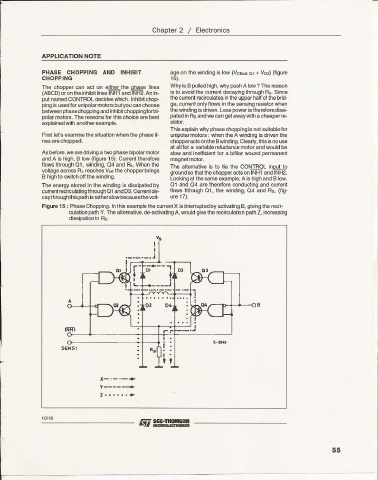
Figure 15 : Phase Chopping. Inthis example the current X is interrupted by activating B, givingthe recir-
culation path Y. The alternative, de-activatingA, would give the recirculation path Z, increasing
dissipation in As.
v.
!
._._._.j I
! ,..-..,-_-_---4-__-,-.-- ,
I 01 .DJ
,
____-J
A
D D4
'
,..,-
INHl
I
a 5-$943
SoENS l i
I
r
Jt_ ._--.-
y-----.......
z· ..
10/18
55