
Page 79 - CNC Robotics
P. 79
CNC Robotics
APPLICATION NOTE
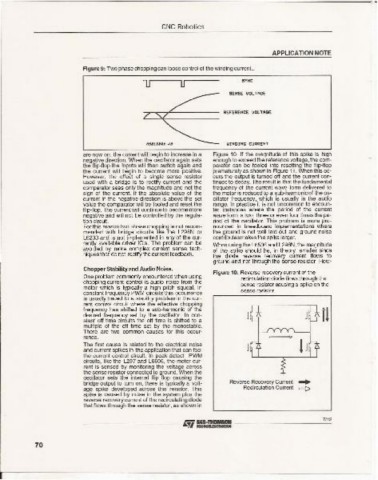
Fig ure 9: Two phase chopping can loose control of the winding current..
lJ u SYMC
SENSE \,IOLTAGE
REFEREHCE UOl lAGE
\lIHOIHG CUAQEHT
are now on , the current will begin to increase in a Figure 10. If the magnitude of this spike is high
negative direction. When the oscillator again sets enough to exceed the reference voltage, the com-
the flip-flop the inputs will then switch again and parator can be fooled into resetting the flip-flop
the current will begin to become more positive. prematurely as shownin Figure 11. When this oc-
However. the effect of a si~9le sense resistor curs the output is turned off and the current con-
used with a bridge is to rectify current and the tinues to decay. The result is that the fundamental
comparator sees on ly the magnitude and not the frequency of the current wave form delivered to
sign of the current. If the absolute value of the the motor is reduced to a sub-harmonicof the os-
current in the negative direction is above the set cillator frequency, which is usually in the audio
value the com parator will be fool ed and reset the range. In practice it is not uncommon to encoun-
flip -flop. The current will continue to become more ter instances where the period of the current
negative and will not be co ntrolled by the regula- wave form is two, three or even four times the pe-
tion circuit. riod of the oscillator. This problem is more pro-
For this reason two phase chopping is not recom- nounced in breadboard implementations where
mended with bridge circuits like the l298N or the ground is not well laid out and ground noise
L6203 and is not implemented in any of the cur- contributes makes the spike larger.
rently available driver IC's. The problem can be When using the L6506 and L298N, the magnitude
avoided by more complex current sense tech- of the spike should be, in theory, smaller since
niques that do not rectify the current feedback. the diode reverse recovery current flows to
ground and not through the sense resistor. How-
Chopper Stability and Audio Noise.
Fig ure 10: Reverse recoverycurrent of the
One problem commonly encountered when using recirculation diode flows through the
chopping current control is audio noise from the sense resistorcausinga spikeon the
motor which is typically a high pitch squeal. In
constant frequency PWM circuits this occurrence sense resistor.
is usually traced to a stability problem in the cur-
rent control circuit where the effective chopping
frequency has shifted to a sub-harmonic of the
desired frequency set by the oscillator. In con-
stant off time circuits the off time is shifted to a
multiple of the off time set by the monoslable.
There are two common causes for this occur-
rence.
The first cause is related to the electrical noise
and current spikes in the application that can fool
the current control circuit. In peak detect PWM
ctrcnts, like the l297 and L6506. the motor cur-
rent is sensed by monitoring the voltage across
the sense resistor connected to ground. When the
oscillator sets the internal flip flop causing the
bridge output to tum on, there is typically a volt- Reverse Recovery Current ....
age spike developed across this resistor. This Recirculation Current c::::;>
spike IS caused by noise in the system plus the
reverse recoverycurrent of the recirculatingdiode
that flows through the sense resistor. as shown in
7/12
- - - - - - - - --- Iifi ~,;,,~ ----- - - -----'--"
70