
Page 82 - CNC Robotics
P. 82
Chapter 2 / Electronics
APPLICATION NOTE
plemented directly using the l297 or L6506. In the comparator.The current cont rol circuit is com-
this mode, ignoring back EMF. the voltage across pletely content to keep operating in this condition.
the coil during the on time (11) when current is in- In fact the circuit may ope rate on one of two sta-
creasing and the recirculation time (12), are: ble conditions depending on the random time
V, = Vs · 2 Vsat • VRsense when the peak curre nt is first reached relative to
the oscillator period.
and
The easiest, and recommended, solution is to ap-
Vz = Vss + 2 VF ply the chopping signal to only one of the phase
The rate of current change is given by (ignoring inputs, as imple mented with the L297, In the
the series resistance): phase chopping mode, or the L6506.
Another solution that works, in some cases, is to
V = L.9.i fix a large minimum duty cycle, in the range of
dt
30%, by applying an external clock signal to the
sync input of the L297 or L6506. In th is configura-
Since the voltage across the coil (V2) durin g the tion the circuit must output at least the rninimrm
recirculation time is more than the voltage (V,) duty cycle during each clock period. This forces
across the coil during the on lime the duty cycle the point where the peak current is detected to be
will, by definition, be greater tha n 50% because 11 later in each cycle and the chopping frequency to
must be greater than 12. When the back EMF 01 lock on the fundamental. The main disadvantage
the motor is considered the duty cycle becomes of this approach is that it sets a higher minirru m
even greater since the back EMF opposes the in- current that can be controlled . The current in the
crease of current during the on time and aides the motor also tends to overshoot during the first few
decay of current. chopping cycles since the actual peak current is
In this conclitionthe control circuit may be content not be sensed during the minimum duty cycle.
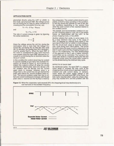
to ope rate stability at one half of the oscillator fre-
que ncy, as shown in Figure 13. As in normal op-
eration, the output is turned off when the cur rent EFFECTS OF BACK EMF
reaches the desired peak value and decays until As ment ioned earlier, the back EMF in a stepper
the oscillator sets the flip-flop and the current motor tends to increase the duty cycl e of the
again starts to increase. However since t1 is chopping drive circuits since it opposes current in-
longer than t2 the current has not yet reached the creased and aids current decay. In extreme,
peak value before the seco nd oscillator pulse oc- cases where the power supply voltage is low
curs. The second oscillator pulse then has no ef- compared to the peak back EMF of the motor, the
fect and current continues to increase until the set duty cycle required when using the phase chop-
peak value is reached and the flip-flop is reset by ping may exceed 50% and the problem with the
Figure 13: When the output duty cycle exceeds 50% the chopping circuit may sinchronize of a
sub-harmonic of the oscillator frequency.
l
Expected Molor c..,....t
Actual Motor current
10112
73