
Page 259 - Cam Design Handbook
P. 259
THB8 9/19/03 7:25 PM Page 247
CAM MECHANISM FORCES 247
100
50
Torque (lb-in.) T in (with spring) T c
0
T in
–50
0 50 100 150 200 250 300 350 400
q
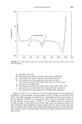
FIGURE 8.25. Inertia torque of the cam T c and the required input torque on the roller crank with and
without the spring.
m c = the mass of the cam
2
R c = the distance from the pivot to the center of mass of the cam
R Fc = the moment arm of the contact force about the cam pivot
R s = the moment arm of the spring force about the cam pivot
I r = the moment of inertia of the roller crank about its center of mass
m r = the mass of the roller crank
R r = the distance from the pivot to the center of mass of the roller crank
r Fc = the moment arm of the contact force about the roller crank pivot
r s = the moment arm of the spring force about the roller crank pivot
Figure 8.25 shows T in as a function of the roller crank position for the single-dwell
mechanism. In this calculation, a constant angular velocity of 30rpm was assumed for the
roller crank. Other properties estimated for the single-dwell prototype were: density of
3
the cam material = 0.04lb/in ; m c = mass of the cam = 0.32lb; I c = moment of inertia of
2
the cam about its center of mass = 1.7264lb - in ; R c = distance from the cam pivot to
its center of mass = 2.2in. Inertia forces of the roller crank were neglected. Figure 8.25
shows the input torque requirement with and without the force-closure spring. The next
step is to optimize the location of the spring and the spring constant to decrease the peak
input torque to improve the performance of the device at high speeds based on the quasi-
static analysis.