
Page 256 - Cam Design Handbook
P. 256
THB8 9/19/03 7:25 PM Page 244
244 CAM DESIGN HANDBOOK
5
4
3 n*
n, n* 2 –2dh/dq
1 –dh/dq
0
n
–1
0 20 40 60 80 100 120 140 160 180
q
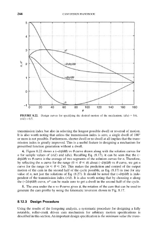
FIGURE 8.22. Design curves for specifying the desired motion of the mechanism; (d/a) = 0.6,
(r/d) = 0.5.
transmission index but also in selecting the longest possible dwell or reversal of motion.
It is also worth noting that unless the transmission index is zero, a single dwell of 180°
or more is not possible. Furthermore, shorter dwell or no dwell at all implies that the trans-
mission index is greatly improved. This is a useful feature in designing a mechanism for
prescribed function generation without a dwell.
4. Figure 8.22 shows a (-dh/dq) vs q curve drawn along with the solution curves for
n for sample values of (r/d) and (d/a). Recalling Eq. (8.17), it can be seen that the (-
dh/dq) vs q curve is the average of two segments of the solution curves for n. Therefore,
by reflecting the n curve for the range (0 q p) about (-dh/dq) vs q curve, we get n
curve for the range (p q 2p). This makes the prediction and control of the output
motion of the cam in the second half of the cycle possible, as Eq. (8.17) is true for any
value of n, not just the solutions of Eq. (8.27). It should be noted that (-dh/dq) is inde-
pendent of the transmission index (r/d). It is also worth noting that by choosing n along
the (-2dh/dq) curve, n* can be made zero to get a dwell in the second half of the cycle.
5. The area under the n vs q curve gives f, the rotation of the cam that can be used to
generate the cam profile by using the kinematic inversion shown in Fig. 8.17.
8.12.3 Design Procedure
Using the results of the foregoing analysis, a systematic procedure for designing a fully
rotatable, roller-crank driven cam mechanism for arbitrary motion specifications is
described in this section. An important design specification is the minimum value the trans-