
Page 252 - Cam Design Handbook
P. 252
THB8 9/19/03 7:25 PM Page 240
240 CAM DESIGN HANDBOOK
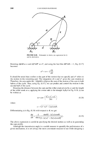
FIGURE 8.18. Schematic to derive an expression for h
and its derivative.
Denoting df/dq as n and df*/dq* as n*, and using the fact that dq*/dq =-1, Eq. (8.17)
becomes
dh
n* + n = -2 .
dq
It should be noted that n refers to the part of the motion that we specify and n* refers to
the motion in the remaining part. The integration of n and n* gives the cam rotation f.
Therefore, the area under the -2dh/dq vs q gives the sum of the motion of the cam in both
halves of the cycle. Thus, using Eq. (8.17), we can predict and control the motion in the
second half of the cycle.
Denoting the distance between the cam and the roller-crank pivots by d, and the length
of the roller crank as a, applying the cosine rule to the triangle A 0B 0A in Fig. 8.18, h can
be written as
Ê d 2 + x 2 - a 2 ˆ
h = cos -1 (8.18)
Ë 2 x ¯
d
where
x = a + d - 2 ad cos .
q
2
2
Differentiating h in Eq. (8.18) with respect to q, we get
dh -1 sin q - ((1 da )cos q)
= . (8.19)
2
dq sin h (1 +(da ) - ( 2 da )cos q) 32
The above expression is useful in specifying the desired motion as well as in generating
the cam profile.
Although the transmission angle is a useful measure to quantify the performance of a
given mechanism, it is not always the most convenient measure to use while designing a