
Page 250 - Cam Design Handbook
P. 250
THB8 9/19/03 7:25 PM Page 238
238 CAM DESIGN HANDBOOK
Roller
Cam profile
Roller
crank Pitch curve
f
q
B
A 0 0
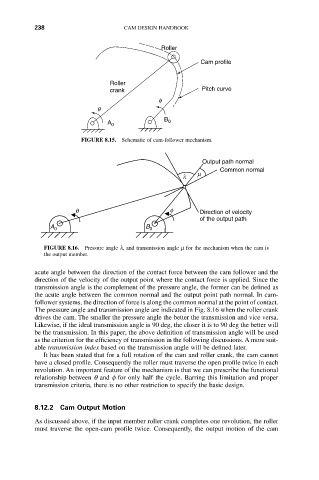
FIGURE 8.15. Schematic of cam-follower mechanism.
Output path normal
Common normal
l m
q f Direction of velocity
of the output path
A 0 B 0
FIGURE 8.16. Pressure angle l, and transmission angle m for the mechanism when the cam is
the output member.
acute angle between the direction of the contact force between the cam follower and the
direction of the velocity of the output point where the contact force is applied. Since the
transmission angle is the complement of the pressure angle, the former can be defined as
the acute angle between the common normal and the output point path normal. In cam-
follower systems, the direction of force is along the common normal at the point of contact.
The pressure angle and transmission angle are indicated in Fig. 8.16 when the roller crank
drives the cam. The smaller the pressure angle the better the transmission and vice versa.
Likewise, if the ideal transmission angle is 90 deg, the closer it is to 90 deg the better will
be the transmission. In this paper, the above definition of transmission angle will be used
as the criterion for the efficiency of transmission in the following discussions. A more suit-
able transmission index based on the transmission angle will be defined later.
It has been stated that for a full rotation of the cam and roller crank, the cam cannot
have a closed profile. Consequently the roller must traverse the open profile twice in each
revolution. An important feature of the mechanism is that we can prescribe the functional
relationship between q and f for only half the cycle. Barring this limitation and proper
transmission criteria, there is no other restriction to specify the basic design.
8.12.2 Cam Output Motion
As discussed above, if the input member roller crank completes one revolution, the roller
must traverse the open-cam profile twice. Consequently, the output motion of the cam