
Page 248 - Cam Design Handbook
P. 248
THB8 9/19/03 7:25 PM Page 236
236 CAM DESIGN HANDBOOK
Weight Output
force torque
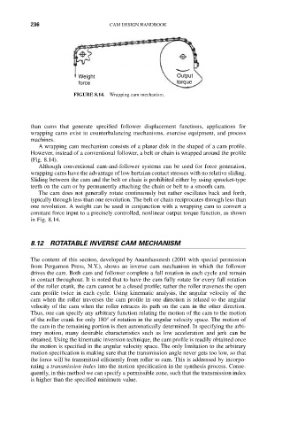
FIGURE 8.14. Wrapping cam mechanism.
than cams that generate specified follower displacement functions, applications for
wrapping cams exist in counterbalancing mechanisms, exercise equipment, and process
machines.
A wrapping cam mechanism consists of a planar disk in the shaped of a cam profile.
However, instead of a conventional follower, a belt or chain is wrapped around the profile
(Fig. 8.14).
Although conventional cam-and-follower systems can be used for force generation,
wrapping cams have the advantage of low hertzian contact stresses with no relative sliding.
Sliding between the cam and the belt or chain is prohibited either by using sprocket-type
teeth on the cam or by permanently attaching the chain or belt to a smooth cam.
The cam does not generally rotate continuously but rather oscillates back and forth,
typically through less than one revolution. The belt or chain reciprocates through less than
one revolution. A weight can be used in conjunction with a wrapping cam to convert a
constant force input to a precisely controlled, nonlinear output torque function, as shown
in Fig. 8.14.
8.12 ROTATABLE INVERSE CAM MECHANISM
The content of this section, developed by Ananthasuresh (2001 with special permission
from Pergamon Press, N.Y.), shows an inverse cam mechanism in which the follower
drives the cam. Both cam and follower complete a full rotation in each cycle and remain
in contact throughout. It is noted that to have the cam fully rotate for every full rotation
of the roller crank, the cam cannot be a closed profile; rather the roller traverses the open
cam profile twice in each cycle. Using kinematic analysis, the angular velocity of the
cam when the roller traverses the cam profile in one direction is related to the angular
velocity of the cam when the roller retraces its path on the cam in the other direction.
Thus, one can specify any arbitrary function relating the motion of the cam to the motion
of the roller crank for only 180° of rotation in the angular velocity space. The motion of
the cam in the remaining portion is then automatically determined. In specifying the arbi-
trary motion, many desirable characteristics such as low acceleration and jerk can be
obtained. Using the kinematic inversion technique, the cam profile is readily obtained once
the motion is specified in the angular velocity space. The only limitation to the arbitrary
motion specification is making sure that the transmission angle never gets too low, so that
the force will be transmitted efficiently from roller to cam. This is addressed by incorpo-
rating a transmission index into the motion specification in the synthesis process. Conse-
quently, in this method we can specify a permissible zone, such that the transmission index
is higher than the specified minimum value.