
Page 245 - Cam Design Handbook
P. 245
THB8 9/19/03 7:25 PM Page 233
CAM MECHANISM FORCES 233
L
dr
rdq
r
a p
dq
T
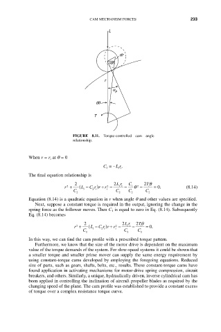
FIGURE 8.11. Torque-controlled cam angle
relationship.
When r = r i at q = 0
C =- L r.
3 ii
The final equation relationship is
2 2 Lr C 2 Tq
)
2
+
2
r + ( L - C r r r - ii - 1 q 2 - i = 0. (8.14)
i
2
i
i
C 2 C 2 C 2 C 2
Equation (8.14) is a quadratic equation in r when angle q and other values are specified.
Next, suppose a constant torque is required in the output, ignoring the change in the
spring force as the follower moves. Then C 1 is equal to zero in Eq. (8.14). Subsequently
Eq. (8.14) becomes
2 2 Lr 2 Tq
r + ( L - C r r r - ii - i = 0.
)
+
2
2
C i 2 i i C C
2 2 2
In this way, we can find the cam profile with a prescribed torque pattern.
Furthermore, we know that the size of the motor drive is dependent on the maximum
value of the torque demands of the system. For slow-speed systems it could be shown that
a smaller torque and smaller prime mover can supply the same energy requirement by
using constant-torque cams developed by employing the foregoing equations. Reduced
size of parts, such as gears, shafts, belts, etc., results. These constant-torque cams have
found application in activating mechanisms for motor-drive spring compression, circuit
breakers, and others. Similarly, a unique, hydraulically driven, inverse cylindrical cam has
been applied in controlling the inclination of aircraft propeller blades as required by the
changing speed of the plane. The cam profile was established to provide a constant excess
of torque over a complex resistance torque curve.