
Page 242 - Cam Design Handbook
P. 242
THB8 9/19/03 7:25 PM Page 230
230 CAM DESIGN HANDBOOK
Normal
L O
a p
Pitch F
curve
N
a p
rw
r
Cam
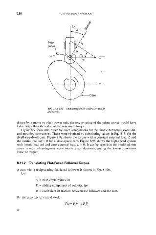
FIGURE 8.8. Translating roller follower velocity
and forces.
driven by a motor or other power unit, the torque rating of the prime mover would have
to be larger than the value of the maximum torque.
Figure 8.9 shows the roller follower comparisons for the simple harmonic, cycloidal,
and modified sine curves. These were obtained by substituting values in Eq. (8.7) for the
dwell-rise-dwell cam. Figure 8.9a shows the torque with a constant external load, L and
the inertia load mÿ = 0 for a slow-speed cam. Figure 8.9b shows the high-speed system
with inertia load mÿ and zero external load, L = 0. It can be seen that the modified sine
curve is most advantageous when inertia loads dominate, giving the lowest maximum
value of torque.
8.11.2 Translating Flat-Faced Follower Torque
A cam with a reciprocating flat-faced follower is shown in Fig. 8.10a.
Let
r b = base circle radius, in
V s = sliding component of velocity, ips
m = coefficient of friction between the follower and the cam.
By the principle of virtual work
Tw = F y m F V
˙
+
n n s
or