
Page 247 - Cam Design Handbook
P. 247
THB8 9/19/03 7:25 PM Page 235
CAM MECHANISM FORCES 235
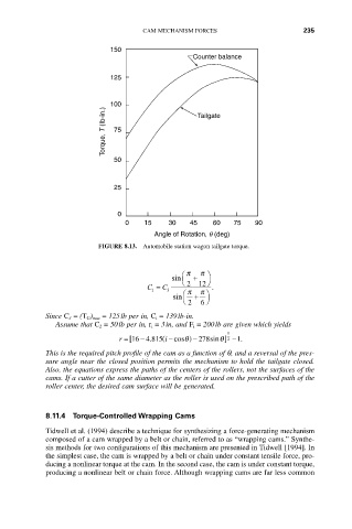
150
Counter balance
125
100 Tailgate
Torque, T (Ib-in.) 75
50
25
0
0 15 30 45 60 75 90
Angle of Rotation, q (deg)
FIGURE 8.13. Automobile station wagon tailgate torque.
Ê p p ˆ
sin +
Ë 2 12 ¯
C = C 3 p p .
1
sin Ê + ˆ
Ë 2 6 ¯
Since C 3 = (T G) max = 125lb per in, C i = 139lb-in.
Assume that C 2 = 50lb per in, r i = 3in, and F i = 200lb are given which yields
1
.
-
r =[16 4 815 ( i - cosq ) - 278sinq ] -1.
2
This is the required pitch profile of the cam as a function of q, and a reversal of the pres-
sure angle near the closed position permits the mechanism to hold the tailgate closed.
Also, the equations express the paths of the centers of the rollers, not the surfaces of the
cams. If a cutter of the same diameter as the roller is used on the prescribed path of the
roller center, the desired cam surface will be generated.
8.11.4 Torque-Controlled Wrapping Cams
Tidwell et al. (1994) describe a technique for synthesizing a force-generating mechanism
composed of a cam wrapped by a belt or chain, referred to as “wrapping cams.” Synthe-
sis methods for two configurations of this mechanism are presented in Tidwell [1994]. In
the simplest case, the cam is wrapped by a belt or chain under constant tensile force, pro-
ducing a nonlinear torque at the cam. In the second case, the cam is under constant torque,
producing a nonlinear belt or chain force. Although wrapping cams are far less common