
Page 246 - Cam Design Handbook
P. 246
THB8 9/19/03 7:25 PM Page 234
234 CAM DESIGN HANDBOOK
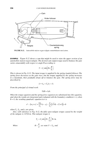
Cam
Roller follower
Tailgate Counterbalancing
spring
FIGURE 8.12. Automobile station wagon tailgate counterbalance mechanism.
EXAMPLE Figure 8.12 shows a cam that might be used to raise the upper section of an
automobile station wagon tailgate. The desired cam output torque used to balance the gate
varies sinusoidally with respect to angle q according to
Ê p ˆ
T = C sin q + 6 ¯ .
Ë
1
This is shown in Fig. 8.13. The input torque is supplied by the spring-loaded follower. The
spring force decreases as the gate rises, but the torque supplied by the spring increases
to a maximum, then gradually drops off to balance the gate. The spring force may be
described by
(
L = L - C r - r).
i
2
1
From the principal of virtual work
Tdq = Ldr.
When the torque equation and the spring-force equation are substituted into this equation,
and when the results are integrated and evaluated with the boundary condition r = r i when
q= 0, the resulting quadratic equation in r is
2 L C
r - 2 rr + r + 1 ( rr ) - [ 31- C) + 5] = 0
(
1
-
2
2
i i i
C C
2 2
when C 2, L i, and r i are given.
Also, with reference to Fig. 8.12, the fully open tailgate torque caused by the weight
of the tailgate is 125lb-in. This tailgate torque is
Ê p ˆ
T = C sin q + lb-in.
G 3 Ë 12 ¯
p
When q = , we want T = T G, and
2