
Page 243 - Cam Design Handbook
P. 243
THB8 9/19/03 7:25 PM Page 231
CAM MECHANISM FORCES 231
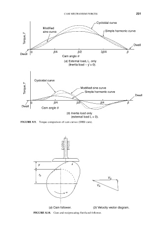
Cycloidal curve
Modified
sine curve Simple harmonic curve
Torque,T
Dwell
0 b/4 b/2 3b/4 b
Dwell
Cam angle q
(a) External load, L, only
··
(Inertia load ~ y = 0).
Cycloidal curve
Torque,T Modified sine curve
Simple harmonic curve
Dwell
0 b/4 b/2 b/4 b
Dwell
Cam angle q
(b) Inertia load only
(external load L = 0).
FIGURE 8.9. Torque comparison of cam curves (DRD cam).
y A
r b
V S
V A
w
(a) Cam follower. (b) Velocity vector diagram.
FIGURE 8.10. Cam and reciprocating flat-faced follower.