Page 238 - Cam Design Handbook
P. 238

THB8  9/19/03  7:25 PM  Page 226

          226                      CAM DESIGN HANDBOOK

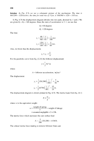
          Solution In  Fig.  8.7a we  see  a  schematic  picture  of  the  mechanism.  The  time  is
                                               1
          60/1200 = 1/20sec/rev; the time for total rise of 1 / 4 in. is 160/360 ¥ 1/20 = 1/45sec.
             In Fig. 8.7b the displacement diagram divides into two parts, denoted by 1 and 2. We
          are given q 1 + q 2 = 160 degrees. Since the ratio of acceleration is 3:1, we see that
                                     q =  40 degrees
                                      1
                                     q = 120 degrees
                                      2
          The time

                                      40 Ê  1  ˆ  1
                                  t =        =    sec
                                   1     Ë  ¯
                                     160 45   180
                                      120 Ê  1  ˆ  1
                                  t =        =   sec.
                                         Ë
                                   2
                                      160 45 ¯  60
          Also, we know that the displacements
                                              1
                                       y +  y = 1 .
                                           2
                                        1
                                              4
          For the parabolic curve from Eq. (2.24) the follower displacement
                                          1
                                       y =   t Ain
                                             2
                                          2
          where
                               A = follower accceleration, in sec 2
          The displacement

                                    1      Ê  1  ˆ  2  5
                                      20200)
                                y =  ( ,          =  in
                                 1
                                    2      Ë 180 ¯  16
                                    1     Ê  1  2  15
                                y =  ( 6750)  ˆ  =  in.
                                 2        Ë  ¯
                                    2      60    16
          The displacement diagram is shown plotted in Fig. 8.7b. The inertia loads from Eq. (8.1)
                                            w
                                        F =   y ˙˙
                                         i
                                            g
          where w is the equivalent weight:
                                weight of spring
                            w =             + weight of linkage
                                     3
                              = assumed negligible  + = lb.2  2
          The inertia force which increases the cam surface load
                                     2
                                 F =    (20 200,  ) =+104lb.
                                  i
                                    386
          The critical inertia force tending to remove follower from cam
   233   234   235   236   237   238   239   240   241   242   243