
Page 236 - Cam Design Handbook
P. 236
THB8 9/19/03 7:25 PM Page 224
224 CAM DESIGN HANDBOOK
w a
g
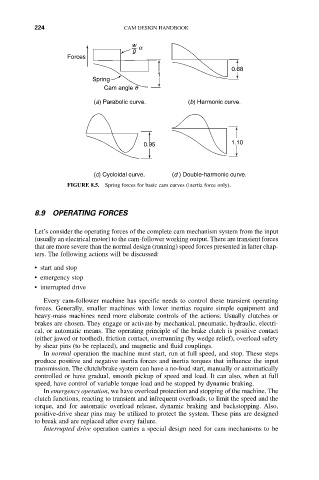
Forces
0.68
1
Spring
Cam angle q
(a) Parabolic curve. (b) Harmonic curve.
0.95 1.10
(c) Cycloidal curve. (d ) Double-harmonic curve.
FIGURE 8.5. Spring forces for basic cam curves (inertia force only).
8.9 OPERATING FORCES
Let’s consider the operating forces of the complete cam mechanism system from the input
(usually an electrical motor) to the cam-follower working output. There are transient forces
that are more severe than the normal design (running) speed forces presented in latter chap-
ters. The following actions will be discussed:
• start and stop
• emergency stop
• interrupted drive
Every cam-follower machine has specific needs to control these transient operating
forces. Generally, smaller machines with lower inertias require simple equipment and
heavy-mass machines need more elaborate controls of the actions. Usually clutches or
brakes are chosen. They engage or activate by mechanical, pneumatic, hydraulic, electri-
cal, or automatic means. The operating principle of the brake clutch is positive contact
(either jawed or toothed), friction contact, overrunning (by wedge relief), overload safety
by shear pins (to be replaced), and magnetic and fluid couplings.
In normal operation the machine must start, run at full speed, and stop. These steps
produce positive and negative inertia forces and inertia torques that influence the input
transmission. The clutch/brake system can have a no-load start, manually or automatically
controlled or have gradual, smooth pickup of speed and load. It can also, when at full
speed, have control of variable torque load and be stopped by dynamic braking.
In emergency operation, we have overload protection and stopping of the machine. The
clutch functions, reacting to transient and infrequent overloads, to limit the speed and the
torque, and for automatic overload release, dynamic braking and backstopping. Also,
positive-drive shear pins may be utilized to protect the system. These pins are designed
to break and are replaced after every failure.
Interrupted drive operation carries a special design need for cam mechanisms to be