
Page 235 - Cam Design Handbook
P. 235
THB8 9/19/03 7:25 PM Page 223
CAM MECHANISM FORCES 223
Displacement
+
–
Follower
inertia
Spring
force force
Load margin
(critical point)
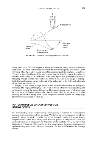
FIGURE 8.4. Spring critical design point (inertia force only).
spring force curve. The critical point is where the inertia and spring forces are closest to
each other. This point occurs in the vicinity of the maximum negative acceleration. Jump
will occur when the negative inertia force of the system exceeds the available spring force.
The spring force should exceed the total external load by 30 to 50 percent, depending on
the mass and elasticity of the mechanism. Note, a small percent of spring load is to include
the spring strength loss that will occur over a period of use. Also, in the design of a spring-
loaded system the spring should be located at the farthest part of the follower to eliminate
all backlash and clearances.
Surging, or coil flutter, at high speeds is the common manifestation of spring per-
formance. The surging of the spring is the result of forced vibration waves advancing and
reflecting throughout the length of the spring. Thus, a complicated series of vibrations may
be continually reinforcing and partially canceling each other during the action, further
reducing the effective spring force. A multi-degree-of-freedom system for spring surge
phenomenon is discussed in Chap. 12.
8.8 COMPARISON OF CAM CURVES FOR
SPRING DESIGN
For inertia loading, let us compare spring sizes necessary to constrain the follower to the
cam during the complete cycle of operation. The following basic curves are considered:
parabolic, simple harmonic, cycloidal, and double harmonic. In Fig. 8.5 we see that the
simple harmonic curve has a spring force that is 68 percent of the parabolic curve, the
cycloidal curve has a spring force of 95 percent of the parabolic curve, and the double
harmonic is 110 percent of the parabolic curve value. Among the curves compared, the
cycloidal cam gives the smoothest force variation. For further information see Jennings
(1941).