
Page 232 - Cam Design Handbook
P. 232
THB8 9/19/03 7:25 PM Page 220
220 CAM DESIGN HANDBOOK
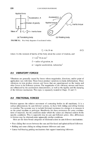
Applied force
Acceleration, a
Acceleration, A
Center of gravity Applied torque
T = I , Inertia torque
a
a
w
Mass m F = A = Inertia force
a g
(a) Translating body. (b) Rotating body.
FIGURE 8.1. Free-body diagrams of accelerated bodies.
T = Ia, lb-in (8.2)
a
where I is the moment of inertia of the body about the center of rotation, and
I = mk 2 lb-in-sec 2
k = radius of gyration, in
a = angular acceleration, radians/sec 2
8.5 VIBRATORY FORCES
Vibrations are generally caused by forces whose magnitudes, directions, and/or point of
application vary with time. These forces produce variations in elastic deformations. These
vibrations in turn produce stresses and forces that are superimposed on the inertia and
other forces in the follower systems. The magnitudes of the vibratory stresses and forces
are influenced by the acceleration characteristics, as well as the rigidity and the damping
of the follower mechanism. This topic is separately treated in Chaps. 12 and 13.
8.6 FRICTIONAL FORCES
Friction opposes the relative movement of contacting bodies in all machinery. It is a
surface phenomenon. In cam-follower systems, we have both sliding and rolling friction
to consider. The accurate way to include frictional resistance in a design is to measure it
on the actual machine or prototype. Handbooks list these resistances for some combina-
tions of materials, but the conditions under which the values are obtained seldom fit the
specific conditions. This is especially true in cam and follower action. Also, differences
in friction may be obtained under apparently similar conditions.
Here are the three broad categories of frictional action in cam-follower mechanisms:
• Pure sliding that occurs between the cam and flat-faced and spherical-faced followers
• Rolling and some sliding in rolling-element followers and cams
• Linear ball-bearing guiding mechanisms that support translating followers