
Page 251 - Cam Design Handbook
P. 251
THB8 9/19/03 7:25 PM Page 239
CAM MECHANISM FORCES 239
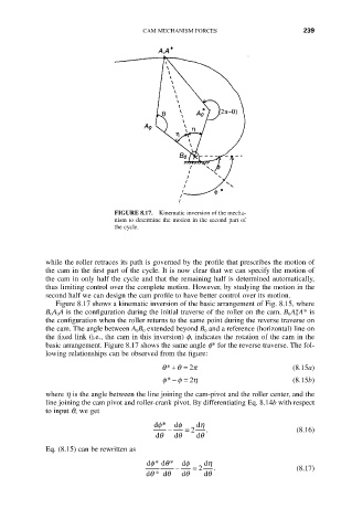
FIGURE 8.17. Kinematic inversion of the mecha-
nism to determine the motion in the second part of
the cycle.
while the roller retraces its path is governed by the profile that prescribes the motion of
the cam in the first part of the cycle. It is now clear that we can specify the motion of
the cam in only half the cycle and that the remaining half is determined automatically,
thus limiting control over the complete motion. However, by studying the motion in the
second half we can design the cam profile to have better control over its motion.
Figure 8.17 shows a kinematic inversion of the basic arrangement of Fig. 8.15, where
B 0A 0A is the configuration during the initial traverse of the roller on the cam. B 0 A 0 *A* is
the configuration when the roller returns to the same point during the reverse traverse on
the cam. The angle between A 0B 0 extended beyond B 0 and a reference (horizontal) line on
the fixed link (i.e., the cam in this inversion) f, indicates the rotation of the cam in the
basic arrangement. Figure 8.17 shows the same angle f* for the reverse traverse. The fol-
lowing relationships can be observed from the figure:
q* + q = 2 p (8.15a)
f* - f = 2 h (8.15b)
where h is the angle between the line joining the cam-pivot and the roller center, and the
line joining the cam pivot and roller-crank pivot. By differentiating Eq. 8.14b with respect
to input q, we get
df* df dh
- = 2 . (8.16)
dq dq dq
Eq. (8.15) can be rewritten as
df* dq* df dh
- = 2 . (8.17)
dq * dq dq dq