
Page 253 - Cam Design Handbook
P. 253
THB8 9/19/03 7:25 PM Page 241
CAM MECHANISM FORCES 241
A
m
P
a
q r
f
b
d C
A o B o y
x
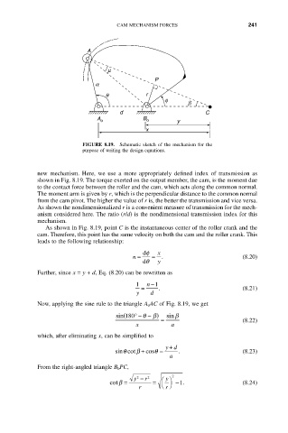
FIGURE 8.19. Schematic sketch of the mechanism for the
purpose of writing the design equations.
new mechanism. Here, we use a more appropriately defined index of transmission as
shown in Fig. 8.19. The torque exerted on the output member, the cam, is the moment due
to the contact force between the roller and the cam, which acts along the common normal.
The moment arm is given by r, which is the perpendicular distance to the common normal
from the cam pivot. The higher the value of r is, the better the transmission and vice versa.
As shown the nondimensionalized r is a convenient measure of transmission for the mech-
anism considered here. The ratio (r/d) is the nondimensional transmission index for this
mechanism.
As shown in Fig. 8.19, point C is the instantaneous center of the roller crank and the
cam. Therefore, this point has the same velocity on both the cam and the roller crank. This
leads to the following relationship:
df x
n = = . (8.20)
dq y
Further, since x = y + d, Eq. (8.20) can be rewritten as
1 n - 1
= . (8.21)
y d
Now, applying the sine rule to the triangle A 0 AC of Fig. 8.19, we get
(
sin 180∞- q - ) b sin b
= (8.22)
x a
which, after eliminating x, can be simplified to
yd
+
q
sin cotb + cosq = . (8.23)
a
From the right-angled triangle B 0PC,
y
y 2 - r 2 Ê ˆ 2
cotb = = -1 . (8.24)
r Ë ¯
r