
Page 258 - Cam Design Handbook
P. 258
THB8 9/19/03 7:25 PM Page 246
246 CAM DESIGN HANDBOOK
FIGURE 8.23. Force closure for the mechanism
using a spring.
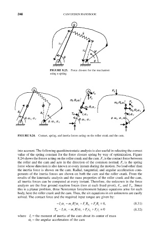
FIGURE 8.24. Contact, spring, and inertia forces acting on the roller crank and the cam.
into account. The following quasikinetostatic analysis is also useful in selecting the correct
value of the spring constant for the force closure spring by way of optimization. Figure
8.24 shows the forces acting on the roller crank and the cam. F c is the contact force between
the roller and the cam and acts in the direction of the common normal. F s is the spring
force whose direction is also known at every instant during the motion. No load other than
the inertia force is shown on the cam. Radial, tangential, and angular acceleration com-
ponents of the inertia forces are shown on both the cam and the roller crank. From the
results of the kinematic analysis and the mass properties of the roller crank and the cam,
all inertia forces can be computed at every instant. Therefore, the unknown in the force
analysis are the four ground reaction forces (two at each fixed pivot), F c, and T in. Since
this is a planar problem, three Newtonian force/moment balance equations arise for each
body, here the roller crank and the cam. Thus, the six equations in six unknowns are easily
solved. The contact force and the required input torque are given by:
2
-I a c - m R a c + F R F c + F R s = 0, (8.31)
c
s
c
c
c
T - a - m R a + F r + F r = 0 (8.32)
2
I
in r r r r r c F c s s
where I c = the moment of inertia of the cam about its center of mass
a c = the angular acceleration of the cam