
Page 260 - Cam Design Handbook
P. 260
THB8 9/19/03 7:25 PM Page 248
248 CAM DESIGN HANDBOOK
5
4
Q*
n*
3
P
P
2
R*
1 – dh/dq
S
R
0
n specified
–1
n
–2
–3
0 50 100 150 200 250 300 350 400
q
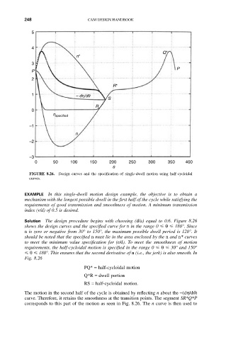
FIGURE 8.26. Design curves and the specification of single-dwell motion using half-cycloidal
curves.
EXAMPLE In this single-dwell motion design example, the objective is to obtain a
mechanism with the longest possible dwell in the first half of the cycle while satisfying the
requirements of good transmission and smoothness of motion. A minimum transmission
index (r/d) of 0.5 is desired.
Solution The design procedure begins with choosing (d/a) equal to 0.6. Figure 8.26
shows the design curves and the specified curve for n in the range 0 q 180°. Since
n is zero or negative from 30° to 150°, the maximum possible dwell period is 120°. It
should be noted that the specified n must lie in the area enclosed by the n and n* curves
to meet the minimum value specification for (r/d). To meet the smoothness of motion
requirements, the half-cycloidal motion is specified in the range 0 q 30° and 150°
q 180°. This ensures that the second derivative of n (i.e., the jerk) is also smooth. In
Fig. 8.26
PQ* = half-cycloidal motion
Q*R = dwell portion
RS = half-cycloidal motion.
The motion in the second half of the cycle is obtained by reflecting n about the -(dh/dq)
curve. Therefore, it retains the smoothness at the transition points. The segment SR*Q*P
corresponds to this part of the motion as seen in Fig. 8.26. The n curve is then used to