
Page 265 - Cam Design Handbook
P. 265
THB9 9/19/03 7:26 PM Page 253
CAM MATERIALS AND LUBRICATION 253
metallurgy and heat treatment, lubricant rheology and chemistry, surface topography
and geometry, and applied contact load (stress). These machine components also have
commonly related manufacturing requirements. Hence, they share similar manufacturing
technology and engineering analysis.
Specifically much knowledge is now compiled to solve materials problems of rolling-
element bearings and gearing, which is relevant to the needs of the cam-follower designer.
This is because cams, rolling bearings, and gearing are similar in their performance
applications. All three are heavily loaded, surface-contact moving machine elements
supported by lubricated surfaces, and much of their action is primarily of a rolling nature.
Studying the design analysis, data, and application of rolling-element bearings and gearing
will be of distinct value in optimizing the materials and lubrication of cam-follower
mechanisms.
To date, the ultimate material design data is: ball bearings have a finite fatigue life that
is subject to wide fluctuations of life, while gears have a unified theory of surface life
within a limited range of sizes. Zaretsky (1997) and Hamrock and Dawson (1981) are
excellent sources of information for the tribology of gearing and bearings. Zaretsky is at
the National Aeronautics and Space Agency (NASA) in Cleveland, Ohio where in the past
45 years engineers have contributed significantly to the reliability and life of bearings
and gearing. This information is valuable to the study of cam-follower machinery. There-
fore, this chapter contains the latest information on rolling element bearings and gearing,
which could be applied at the designer’s discretion to specific optimized cam-follower
systems.
9.2 ELASTIC CONTACT THEORY
Hertz (1882, 1895) established the state of stress and strain between two contacting elastic
bodies. In this section we present two cases: (a) two crowned rollers and (b) two
cylindrical rollers.
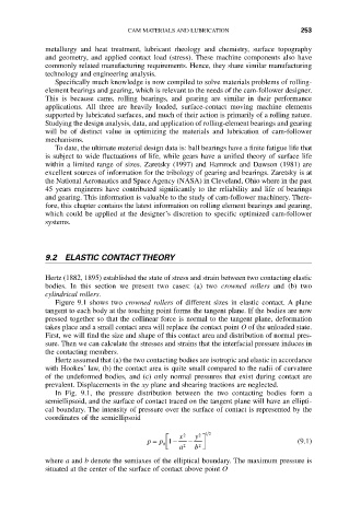
Figure 9.1 shows two crowned rollers of different sizes in elastic contact. A plane
tangent to each body at the touching point forms the tangent plane. If the bodies are now
pressed together so that the collinear force is normal to the tangent plane, deformation
takes place and a small contact area will replace the contact point O of the unloaded state.
First, we will find the size and shape of this contact area and distribution of normal pres-
sure. Then we can calculate the stresses and strains that the interfacial pressure induces in
the contacting members.
Hertz assumed that (a) the two contacting bodies are isotropic and elastic in accordance
with Hookes’ law, (b) the contact area is quite small compared to the radii of curvature
of the undeformed bodies, and (c) only normal pressures that exist during contact are
prevalent. Displacements in the xy plane and shearing tractions are neglected.
In Fig. 9.1, the pressure distribution between the two contacting bodies form a
semiellipsoid, and the surface of contact traced on the tangent plane will have an ellipti-
cal boundary. The intensity of pressure over the surface of contact is represented by the
coordinates of the semiellipsoid
2
È x 2 y ˘ 12
p = p 1 - a 2 - b ˚ ˙ (9.1)
Í
0
Î
2
where a and b denote the semiaxes of the elliptical boundary. The maximum pressure is
situated at the center of the surface of contact above point O