
Page 268 - Cam Design Handbook
P. 268
THB9 9/19/03 7:26 PM Page 256
256 CAM DESIGN HANDBOOK
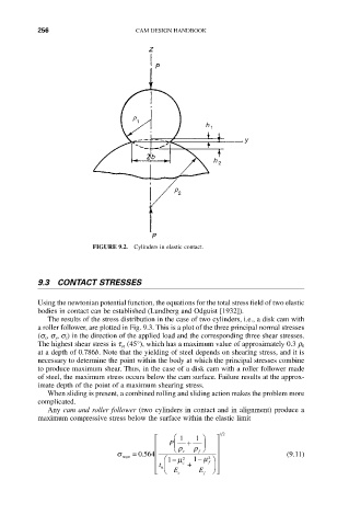
FIGURE 9.2. Cylinders in elastic contact.
9.3 CONTACT STRESSES
Using the newtonian potential function, the equations for the total stress field of two elastic
bodies in contact can be established (Lundberg and Odguist [1932]).
The results of the stress distribution in the case of two cylinders, i.e., a disk cam with
a roller follower, are plotted in Fig. 9.3. This is a plot of the three principal normal stresses
(s x, s y, s z) in the direction of the applied load and the corresponding three shear stresses.
The highest shear stress is t yz (45°), which has a maximum value of approximately 0.3 r 0
at a depth of 0.786b. Note that the yielding of steel depends on shearing stress, and it is
necessary to determine the point within the body at which the principal stresses combine
to produce maximum shear. Thus, in the case of a disk cam with a roller follower made
of steel, the maximum stress occurs below the cam surface. Failure results at the approx-
imate depth of the point of a maximum shearing stress.
When sliding is present, a combined rolling and sliding action makes the problem more
complicated.
Any cam and roller follower (two cylinders in contact and in alignment) produce a
maximum compressive stress below the surface within the elastic limit
12
È Ê 1 1 ˆ ˘
Í P Á Ë r + r ¯ ˜ ˙
s = . 0564 Í c f ˙ (9.11)
max 2
Í Ê1 - m 2 1 - m ˆ ˙
f
t c +
Í h Á ˜ ˙
Î Ë E c E f ¯ ˚