
Page 267 - Cam Design Handbook
P. 267
THB9 9/19/03 7:26 PM Page 255
CAM MATERIALS AND LUBRICATION 255
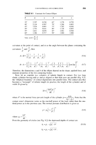
TABLE 9.1 Constants for Contact Ellipse
q m n q m n
35° 2.397 0.530 65° 1.378 0.759
40° 2.136 0.567 70° 1.284 0.802
45° 1.926 0.604 75° 1.202 0.846
50° 1.754 0.641 80° 1.128 0.893
55° 1.611 0.678 85° 1.061 0.944
60° 1.486 0.717 90° 1.000 1.000
B - A
Note: cosq =
B + A
curvature at the point of contact, and y as the angle between the planes containing the
1 1
curvatures and , then
r r¢
1 Ê 1 1 1 1 ˆ
AB = Á + + + ˜ (9.6)
+
2 Ë r ¢ r r r ¢ ¯
1 1 2 2
2 2 12
1 Ê È 1 1 ˆ Ê 1 1 ˆ Ê 1 1 ˆÊ 1 1 ˆ ˘
-
BA = Á Í - ˜ + Á - ˜ + Á 2 - ˜Á - ˜ cos 2y ˙ . (9.7)
2 Î Ë r 1 r 1 ¢ ¯ Ë r 2 r ¢ ¯ Ë r 1 r ¢ ¯Ë r 2 r 2 ¢ ¯ ˚
1
2
Therefore, the dimensions a and b of the ellipse depend on the shape, applied force, and
material properties of the two contacting bodies.
Next, let us consider two cylinders of infinite length in contact. For two long
elastic cylinders having radii r 1 and r 2 aligned so that their axes are parallel (Fig. 9.2),
the “elliptical boundary” of contact degenerates into parallel lines. The contact area thus
becomes a “rectangle” of infinite length (in practice, the length of the cylinder) and of
width 2b given by
Ê 16P¢r ˆ 12
2b = (9.8)
Ë p E ¯
rr
where P¢ is the normal force per unit length of the cylinder r = 1 2 . Note that the
( r + r )
1 2
contact zone’s dimension varies as the one-half power of the load, rather than the one-
third power as in the previous case. The normal pressure distribution is given as
12
2
Ê y ˆ
p = p 1 - (9.9)
0 Ë b 2 ¯
2 P¢
where p = .
0
p b
From the geometry of circles (see Fig. 9.2) the depressed depths of contact are
h = r 1 - r 1 2 - b 2 (9.10)
1
h = r 2 - r 2 2 - b .
2
2