
Page 269 - Cam Design Handbook
P. 269
THB9 9/19/03 7:26 PM Page 257
CAM MATERIALS AND LUBRICATION 257
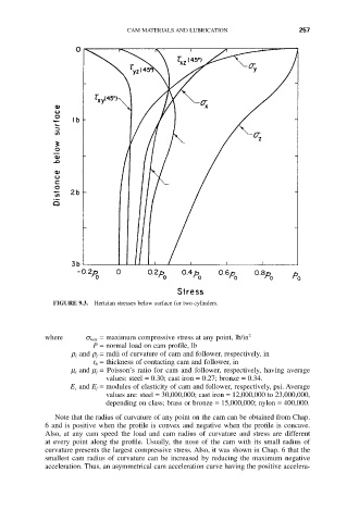
FIGURE 9.3. Hertzian stresses below surface for two cylinders.
where s max = maximum compressive stress at any point, lb/in 2
P = normal load on cam profile, lb
r c and r f = radii of curvature of cam and follower, respectively, in
t h = thickness of contacting cam and follower, in
m c and m f = Poisson’s ratio for cam and follower, respectively, having average
values: steel = 0.30; cast iron = 0.27; bronze = 0.34.
E c and E f = modules of elasticity of cam and follower, respectively, psi. Average
values are: steel = 30,000,000; cast iron = 12,000,000 to 23,000,000,
depending on class; brass or bronze = 15,000,000; nylon = 400,000.
Note that the radius of curvature of any point on the cam can be obtained from Chap.
6 and is positive when the profile is convex and negative when the profile is concave.
Also, at any cam speed the load and cam radius of curvature and stress are different
at every point along the profile. Usually, the nose of the cam with its small radius of
curvature presents the largest compressive stress. Also, it was shown in Chap. 6 that the
smallest cam radius of curvature can be increased by reducing the maximum negative
acceleration. Thus, an asymmetrical cam acceleration curve having the positive accelera-