
Page 271 - Cam Design Handbook
P. 271
THB9 9/19/03 7:26 PM Page 259
CAM MATERIALS AND LUBRICATION 259
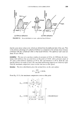
(a) Without deflection. (b) With deflection.
FIGURE 9.5. Stress distribution on cam—spherical-faced follower.
that the same stress values exist, which are shifted from the deflected side of the cam. This
is the primary advantage of a spherical follower as compared to the serious stress increase
exhibited with the cylindrical roller or flat-faced follower. The spherical radii used are
from 10 in to 300 in.
EXAMPLE The nose of a cam has a radius of curvature of 1/4 in. At 1200rpm, the trans-
lating roller-follower has an axial force at this point of 132lb, with a pressure angle of
20° and a roller-follower diameter of 3/4 in. The cam thickness is 3/4 in. Both the cam
and the follower are made of steel. The cam shaft and bearing supports are relatively rigid.
Find the maximum compressive stress on the cam nose at this speed.
Solution The force distribution gives the normal force on the cam surface
132
P = =1401b.
cos 20
From Eq. (9.11), the maximum compressive stress at this point
12
È Ê 1 1 ˆ ˘
Í P Á Ë r + r ¯ ˜ ˙
s = . 0564 Í e f ˙
max 2
Í Ê1 - m 2 1 - m ˆ ˙
f
t c +
Í h Á ˜ ˙
Î Ë E e E f ¯ ˚
12
È Ê ˆ ˘
Í Á 1 1 ˜ ˙
Í 140 Á 3 + 1 ˜ ˙
Í Á Ë ˜ ¯ ˙
s max = . 0564 Í 8 4 ˙ = 801 8001, bin 2
-
-
.
.
Í Í 3 Ê 103 2 103 2 ˆ ˙
Í 4 Á Ë 3010 6 + 3010 6 ˜ ¯ ˙
¥
¥
Í ˙
Í ˙
Î ˚