
Page 270 - Cam Design Handbook
P. 270
THB9 9/19/03 7:26 PM Page 258
258 CAM DESIGN HANDBOOK
tion greater than the negative acceleration will reduce the nose stresses and the size of the
compression spring needed.
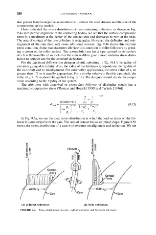
Hertz indicated the stress distribution of two contacting cylinders; as shown in Fig.
9.4a with perfect alignment of the contacting bodies, we see that the surface compressive
stress is a maximum at the center of the contact area and decreases to zero at the ends.
The area of contact of the two cylinders is rectangular. However, the deflection and mis-
alignment of the cam shaft will cause additional stresses. Fig. 9.4b shows this extreme
stress condition. Some manufacturers alleviate this condition in roller followers by grind-
ing a crown on the roller surface. The automobile cam has a taper ground on its surface
of a few thousandths of an inch over the cam width to give a more uniform stress distri-
bution to compensate for the camshaft deflection.
For the flat-faced follower the designer should substitute in Eq. (9.11) its radius of
curvature r f equal to infinity. Also, the value of the thickness t h depends on the rigidity of
the cam shaft and its misalignment. For automotive applications, the stress value of t n no
greater than 1/2 in is usually appropriate. For a similar relatively flexible cam shaft, the
value of t h £ 1/2 in should be applied to Eq. (9.11). The designer should decide the proper
value according to the rigidity of his system.
The disk cam with spherical or crown-face follower of dissimilar metals has a
maximum compressive stress (Thomas and Hoerch [1930] and Turkish [1946])
23
È 2 + 1 ˘
Í ˙
. 00469 1 3 r r
P
s = Í f c ˙ . (9.12)
max . 0237 2 1 - m ˙
2
Ê r ˆ Í 1 - m c + f
f
Á1 + ˜ Í ˙
Ë r ¯ Î E E ˚
c e f
In Fig. 9.5a, we see the ideal stress distribution in which the load or stress on the fol-
lower is symmetrical with the cam. The area of contact has an elliptical shape. Figure 9.5b
shows the stress distribution of a cam with extreme misalignment and deflection. We see
(a) Without deflection. (b) With deflection.
FIGURE 9.4. Stress distribution on cam—cylindrical roller and flat-faced followers.