
Page 471 - Cam Design Handbook
P. 471
THB14 9/19/03 7:58 PM Page 459
SPECIAL CAM MECHANISMS 459
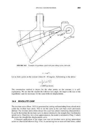
FIGURE 14.5. Example of logarithmic spiral with pure rolling action, full scale.
bq
r-= ae .
Let us find a point on the contour where q = 10 degrees. Substituting in the above
1 Ê 1 ˆÊ 10p ˆ
r = e tan 20 ¯Ë 180 ¯
Ë
2
.
= 0805 in shown.
The construction method is shown for the other points on the contour; it is self-
explanatory. We see that the smaller the follower face angle, the larger is the size of the
logarithmic cam toe necessary for the same follower displacement.
14.4 INVOLUTE CAM
The involute curve (Shaw, 1933) is generated by a string end unwinding from a fixed circle
called the involute base circle. This is not the same as the cam base circle previously
defined. The involute curve when chosen for a cam has certain interesting characteristics.
It can be shown that the involute curve is almost identical to the straight-line (Archimedes
spiral) curve. Therefore, for a close approximation, the reader is referred to Chap. 2 which
discusses the straight-line displacement curve.
A frequent application of the wiper cam uses an involute curve giving intermittent
action to a flat-faced follower (Fig. 14.6). A cam having two or more involute lobes, called