
Page 466 - Cam Design Handbook
P. 466
THB14 9/19/03 7:58 PM Page 454
454 CAM DESIGN HANDBOOK
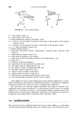
FIGURE 14.1. Cam-modulated linkages.
R r = roller-follower radius, in
R w = mean radius of pin wheel, in
T = torque transmitted, tangent to the bodies, 16/in 2
V P/Q = velocity of contact point P on body B with respect to the ground A in the tangent
direction, in/sec
V P/A = velocity of contact point P on body C with respect to the ground A, in/sec
x, x 1, x 2 = input cam angular rotation, rad
y = follower displacement, in
y e = equivalent mechanism follower displacement measured from crank-end dead
center, in
Y = output follower angular rotation, rad
a = angle between tangents to cam contour
e = crank angle rotation (equivalent mechanism) for displacement y e , rad
-1
f = angle tan m
m = coefficient of friction position, in
q 0 = angle rotated by the output driven member, deg
q = cam angle rotation for displacement y, rad
q t = cam angle to a point on straight-side flank, deg
q i = the angle rotated by input driver, deg
r i = radius to point of contact at angle q i , in
r 0 = radius to point of contact at angle q 0, in
t = angle between connecting rod and follower motion, deg
w = cam and equivalent mechanism angular velocity, rad/sec
In this chapter we discuss some selected special cams and their applications to various
kinds of mechanisms and machinery. Mathematical theories are minimized to emphasize
the practical and inventive aspect of cams as versatile design components.
The cams shown are from the simplest mechanism, the wedge, to elaborate cam-
modulated systems where the follower is located remotely from the basic cam system.
(Figure 14.1 is a schematic drawing of a cam-modulated linkage mechanism used in the
chemical field for measurement.) Summaries of practical cam mechanisms are given by
Freudenstein and Sandor (1996), Grodzinski (1947), and Jones (1967).
14.1 SLIDING BODIES
The action between two contacting bodies may be pure rolling, sliding, or a combination
of both rolling and sliding. Rolling surfaces are a special case of cam and follower action.