
Page 476 - Cam Design Handbook
P. 476
THB14 9/19/03 7:58 PM Page 464
464 CAM DESIGN HANDBOOK
E -
y = (1 cos e) in. (14.9)
e
Differentiating, we find the velocity and acceleration
˙ y = Ew sine ips (14.10)
˙˙ y = Ew 2 cose in sec . (14.11)
2
We see that the eccentric circle size has no effect on the follower action; only the eccen-
tricity, E does. Furthermore, offsetting the line of follower motion from the cam center of
rotation does not change the follower movement.
14.7 CONTOUR-SHAPED RADIAL CAMS
For the radial cams developed elsewhere in this book the desired displacement
characteristics are initially established and then the shape of the cam is mathematically
determined. The analysis of the shape also includes the study of the geometric pressure
angle and curvature of the cam. Then the cam-follower dynamics are investigated if
necessary.
In this section, we will establish the cam contours from known geometric shapes (some-
times blended with other shapes) with limited control of the cam-follower system dynam-
ics. These shapes are rarely utilized in design. In producing a radial cam we can apply any
curve or combination of curves such as straight lines, circular arcs, Archimedes spirals,
involute, logarithmic spirals, ellipses, parabolas, and hyperbolas. As cam-follower mech-
anisms the curves can be utilized as partial or complete rotating bodies in contact with the
follower.
14.7.1 Special Contour
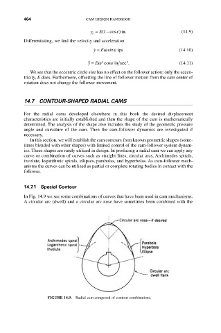
In Fig. 14.9 we see some combinations of curves that have been used in cam mechanisms.
A circular arc (dwell) and a circular arc nose have sometimes been combined with the
FIGURE 14.9. Radial cam composed of contour combinations.