
Page 480 - Cam Design Handbook
P. 480
THB14 9/19/03 7:58 PM Page 468
468 CAM DESIGN HANDBOOK
(a) Cam and follower. (b) Equivalent mechanism.
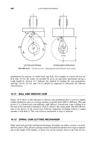
FIGURE 14.13. Circular arc cam—translating flat-faced follower (nose action).
mechanisms for each arc of contact K 0K 1 and K 1K 2. For example, in contact on nose arc
K 1K 2 Fig. 14.13a, the center of curvature B 2 gives an equivalent mechanism having a
crank length E 2. Section 14.7 indicates the method for finding the cam proportions,
and Eqs. (14.9), (14.10), and (14.11) should be employed to determine the follower
characteristics.
14.11 BALL AND GROOVE CAM
Figure 14.14 shows a ball and groove follower cam mechanism that is used in a lightly
loaded mechanism such as a sewing machine at speeds from 2000 to 3000rpm. The cam
groove C is a closed track cam utilizing a ball follower. A round arm A has a sliding fit in
the hole of the ball and is fastened to shaft D, which is the output shaft. The ball follower
runs in the groove of the closed track follower, imparting oscillating motion to output
member A and shaft D. This cam follower mechanism is easy to fabricate.
14.12 SPIRAL CAM CUTTING MECHANISM
Many hand tools provide mechanical advantage. Examples are pliers, scissors, car jacks,
and bolt cutters. They all have a design restriction in that the amount of leverage is depend-
ent on the length of the handles. A spiral cam can be a proper choice to provide the nec-