
Page 477 - Cam Design Handbook
P. 477
THB14 9/19/03 7:58 PM Page 465
SPECIAL CAM MECHANISMS 465
Nose
r n
r n
r 1
Dwell flank
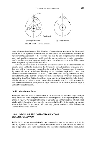
(a) Triple-arc cam. (b) Tangent cam.
FIGURE 14.10. Circular arc cams.
other aforementioned curves. This blending of curves is not acceptable for high-speed
action, since the dynamic characteristics are poor due to the discontinuities in either the
velocity or the acceleration of the follower. Note that the least complex conics applied to
cams such as ellipses, parabolas, and hyperbolas have a continuous evolute, i.e., continu-
ous locus of the center of curvature, to give the acceleration curve continuity. This ensures
more acceptable high-speed characteristics.
However, discontinuities in evolute and acceleration curves exist when blended with
circular noses and flanks. In addition, the Archimedes spiral, logarithmic spiral, and invo-
lute start with an impractical, abrupt slope in which a “bump” occurs with a discontinu-
ity in the velocity of the follower. Blending curves have been employed to correct this
theoretical infinite acceleration. In the past, “triple curve cams” having a circular arc nose,
involute flanks, and a harmonic or parabolic blend into the base circle were popular in the
automotive field. Note that the logarithmic spiral has inherent qualities that make it desir-
able for all sorts of bodies in contact. Applied to the cam form of Fig. 14.9 it provides the
smallest radial cam for a given pressure angle. Moreover, the maximum pressure angle is
constant during the action.
14.7.2 Circular Arc Cams
In the past, the cams were of a combination of circular arcs with or without tangent straight
lines. Even now, some designers utilize these cams regardless of their poor dynamic prop-
erties. In Fig. 14.10a, we see the blending of a circular arc cam having three different sized
circles with r the radius of curvature for the circles. In Fig. 14.10b the circles are blended
with straight lines (tangent cam). All cams may provide motion to roller followers or
convex curved-faced followers.
14.8 CIRCULAR ARC CAM—TRANSLATING
ROLLER FOLLOWER
In Fig. 14.11, we see a typical circular cam composed of arcs having centers at A, B 1, B 2
and B 3. Figures 14.11a and 14.11b show the cam follower in contact over the flank arc
and its equivalent slider crank mechanism. This equivalent mechanism has a crank, radius