
Page 481 - Cam Design Handbook
P. 481
THB14 9/19/03 7:58 PM Page 469
SPECIAL CAM MECHANISMS 469
Cam
groove C
FIGURE 14.14. Ball and groove cam.
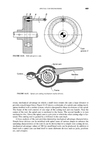
Spiral cam
Cutters Handles
Frame
FIGURE 14.15. Spiral-cam cutting mechanism (rachet driven).
essary mechanical advantage in which a small force rotates the cam a large distance to
provide a much larger force. Figure 14.15 shows a schematic of a spiral-cam cutting mech-
anism doubled with a ratchet system, which is designed for three revolutions of the spiral.
The frame of the tool consists of one edge of the cutting tool and one handle. Near the
center of the tool, the spiral cam is ratcheted to the frame. The second handle is in turn
ratcheted to this. Above the spiral cam is a pin joint to which the other cutting edge is fas-
tened. This cutting tool is guided by a follower in the cam track.
A force analysis of the cam provides interesting mechanical advantage characteristics.
Simple lever devices can be modified with spiral cams of various shapes to enhance the
operating characteristics of the tool. It can be shown that for a simple wire cutting device,
mechanical advantage values of 300 for small hand tools can be produced. In addition to
hand tools a spiral cam can lend itself to more elaborate devices such as jacks, position-
ers, and crimpers.