
Page 483 - Cam Design Handbook
P. 483
THB14 9/19/03 7:58 PM Page 471
SPECIAL CAM MECHANISMS 471
F = F tana = 2 T Dtana (14.17)
c t
where T = the torque transmitted in-lb and D = the effective diameter of the rollers,
inches.
14.14 TWO INDEPENDENT CAMS
IN SERIES (AUTOMOTIVE)
Valve cams for four-stroke-cycle internal combustion engines present special design prob-
lems. They run at speeds of up to 6000rpm with very lightweight flexible follower trains.
These systems have a rise-fall-dwell program with the dwell used to keep the valve sealed
during the cycle. Performance difficulties exist and the demands for high engine per-
formance and good fuel economy have stimulated an interest in variable valve timing
(VVT) for these engines. Variable valve timing is a design system that dynamically
changes the valve timing to be optimized more nearly under all operating conditions.
Dresner and Barkan (1989) have presented a variety of new mechanisms utilizing cams,
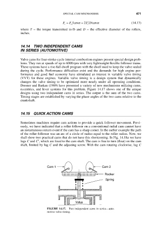
eccentrics, and lever systems for this problem. Figure 14.17 shows one of the unique
designs using two independent cams in series. The output is the sum of the two cams.
Timing stages are established by varying the phase angles of the two cams relative to the
crankshaft.
14.15 QUICK ACTION CAMS
Sometimes machines require cam actions to provide a quick follower movement. Previ-
ously, we have indicated that a roller follower on a conventional radial cam cannot have
an instantaneous return event if the cam has a sharp corner. In the earlier example the path
of the roller follower was an arc of a circle of radius equal to the roller radius. Now, we
shall show two practical cams that do not have this shortcoming. In Fig. 14.18a we have
lugs C and C¢, which are fixed to the cam shaft. The cam is free to turn (float) on the cam
shaft, limited by lug C and the adjusting screw. With the cam rotating clockwise, lug C
Cam 1 Cam 2
Rocker
Spring
Valve
FIGURE 14.17. Two independent cams in series—auto-
motive valve timing.