
Page 487 - Cam Design Handbook
P. 487
THB14 9/19/03 7:58 PM Page 475
SPECIAL CAM MECHANISMS 475
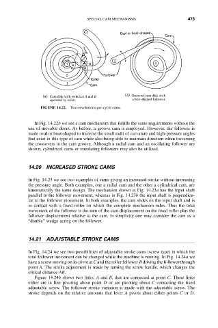
FIGURE 14.22. Two-revolutions-per-cycle cams.
In Fig. 14.22b we see a cam mechanism that fulfills the same requirements without the
use of movable doors. As before, a groove cam is employed. However, the follower is
made oval or boat-shaped to traverse the small radii of curvature and high-pressure angles
that exist in this type of cam while also being able to maintain direction when traversing
the crossovers in the cam groove. Although a radial cam and an oscillating follower are
shown, cylindrical cams or translating followers may also be utilized.
14.20 INCREASED STROKE CAMS
In Fig. 14.23 we see two examples of cams giving an increased stroke without increasing
the pressure angle. Both examples, one a radial cam and the other a cylindrical cam, are
kinematically the same design. The mechanism shown in Fig. 14.23a has the input shaft
parallel to the follower movement, whereas in Fig. 14.23b the input shaft is perpendicu-
lar to the follower movement. In both examples, the cam slides on the input shaft and is
in contact with a fixed roller on which the complete mechanism rides. Thus the total
movement of the follower is the sum of the cam displacement on the fixed roller plus the
follower displacement relative to the cam. In simplicity one may consider the cam as a
“double” wedge acting on the follower.
14.21 ADJUSTABLE STROKE CAMS
In Fig. 14.24 we see two possibilities of adjustable stroke cams (screw type) in which the
total follower movement can be changed while the machine is running. In Fig. 14.24a we
have a screw moving on its pivot at C and the roller follower B driving the follower through
point A. The stroke adjustment is made by turning the screw handle, which changes the
critical distance AB.
Figure 14.24b shows two links, A and B, that are connected at point C. These links
either are in line pivoting about point D or are pivoting about C contacting the fixed
adjustable screw. The follower stroke variation is made with the adjustable screw. The
stroke depends on the relative amounts that lever A pivots about either points C or D.