
Page 490 - Cam Design Handbook
P. 490
THB14 9/19/03 7:58 PM Page 478
478 CAM DESIGN HANDBOOK
Cam Follower
Follower
Cam
Geometrical Follower
center
r = h h
h Cam center
A
r r Cam
B r = h + R 1 C R 1 h h + 2R 1 = r + R 1
A Center A Center
of rotation of rotation
Curved Curved
corners corners
h
h
Path Path
(c) Translating follower–
rounded corner cam.
(a) Equilateral triangle path.
(b) Square path.
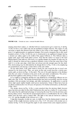
FIGURE 14.26. Circular arc cams—constant-breadth follower.
rotating about their centers, A, with the follower constrained to give a total rise, h. In Fig.
14.26a we have a two-sided cam and an equilateral triangle follower. The radius of cam
curvature r equals the distance from the center to the corner of the triangle. The path of
point A is approximately an equilateral triangle (Not exactly triangular due to the small
rounded corners). In Fig. 14.26b the cam is constructed on an equilateral triangle having
a circular arc radius equal to the width of the square follower, h. This follower takes a
square path, again with small-radius corners. Note that the radius h is equal to the total
displacement of the follower. Obviously, in a similar manner any number of sides may be
used. It should be observed that a practical difficulty exists in that the center line of the
shaft A is on the cam edge, which does not always provide enough space for the shaft.
This shortcoming may be alleviated by the design shown in Fig. 14.26c or by employing
an asymmetrical cam having a small radius at the cam center.
On the other hand, if the outer frame is fixed, the cam would be free to travel con-
strained by the frame track. Thus, any point on the cam would describe a similar geo-
metric path, as shown in Figs. 14.26a and b. The size of the path depends on the distance
from the cam center of rotation to the point on the cam under consideration. This princi-
ple has been applied in the drilling of holes of a polygon of any shape.
Let us analyze a triangular circular arc cam enclosed by a translating follower on two
sides only, Fig. 14.26c. The design discussed here has been successfully used for sewing
machines, film movement, fuel pumps, and other mechanisms. Its application is used in
silent, high speed, lightly loaded, small power mechanisms. Some of these have been in
excellent condition after over 20 years of operation. For further information, see Richards.
(1940, 1941).
The design shown in Fig. 14.26c is more practical than the previous kinds because
space has been provided for the shaft. Furthermore the cam has a radius R 1 in each corner.
This radius has the additional advantage of increasing the wear life over the previous cams
having sharp corners. Note that the actual displacement h is unaffected by the size of this
radius since the basic cam is contour ABC. The sides of the cam are shown at a radius r
= h + R 1, and the breadth of the follower is h + 2R 1.
Using this triangular circular arc cam, we shall show that the displacement is made up
of parts of the simple harmonic motion curve, Fig. 14.27. All action with circular arcs is
similar. In Fig. 14.27a let q equal the angle of cam rotation from some original position.