
Page 489 - Cam Design Handbook
P. 489
THB14 9/19/03 7:58 PM Page 477
SPECIAL CAM MECHANISMS 477
Therefore, minimum stroke will occur with the adjustable screw to the right. In this
instance the arms, A and B, if never in contact with the screw and the lever, will always
pivot about D. Similarly, the maximum stroke will occur when the adjustable screw is at
the left so that the arms will pivot about points C and D. Thus infinite stroke adjustment
is possible within these two ranges.
14.22 CONTROLLED TRANSLATING
CYCLE CAMS
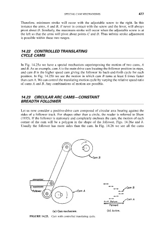
In Fig. 14.25a we have a special mechanism superimposing the motion of two cams, A
and B. As an example, cam A is the main drive cam locating the follower position in steps,
and cam B is the higher speed cam giving the follower its back-and-forth cycle for each
position. In Fig. 14.25b we see the motion in which cam B turns at least 8 times faster
than cam A. We can control the translating motion cycle by varying the relative speed ratio
of cams A and B. Any combinations of motion are possible.
14.23 CIRCULAR ARC CAMS—CONSTANT
BREADTH FOLLOWER
Let us now consider a positive-drive cam composed of circular arcs bearing against the
sides of a follower track. For shapes other than a circle, the reader is referred to Shaw
(1935). If the follower is stationary and completely encloses the cam, the motion of each
corner of the cam will be a polygon in the shape of the follower, Figs. 14.26a and b.
Usually the follower has more sides than the cam. In Fig. 14.26 we see all the cams
FIGURE 14.25. Cam with controlled translating cycle.