
Page 492 - Cam Design Handbook
P. 492
THB14 9/19/03 7:58 PM Page 480
480 CAM DESIGN HANDBOOK
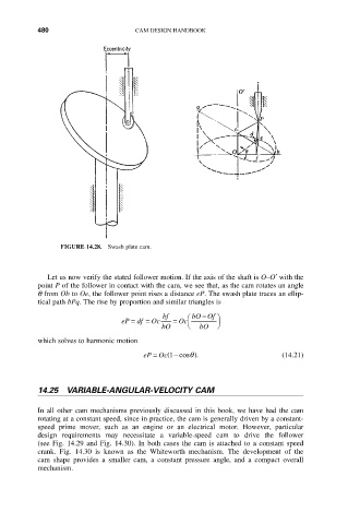
FIGURE 14.28. Swash plate cam.
Let us now verify the stated follower motion. If the axis of the shaft is O–O¢ with the
point P of the follower in contact with the cam, we see that, as the cam rotates an angle
q from Ob to Oe, the follower point rises a distance eP. The swash plate traces an ellip-
tical path bPq. The rise by proportion and similar triangles is
-
bf Ê bO Of ˆ
eP = df = Oc = Oc
bO Ë bO ¯
which solves to harmonic motion
(
eP = Oc - cosq ). (14.21)
1
14.25 VARIABLE-ANGULAR-VELOCITY CAM
In all other cam mechanisms previously discussed in this book, we have had the cam
rotating at a constant speed, since in practice, the cam is generally driven by a constant-
speed prime mover, such as an engine or an electrical motor. However, particular
design requirements may necessitate a variable-speed cam to drive the follower
(see Fig. 14.29 and Fig. 14.30). In both cases the cam is attached to a constant speed
crank. Fig. 14.30 is known as the Whiteworth mechanism. The development of the
cam shape provides a smaller cam, a constant pressure angle, and a compact overall
mechanism.