
Page 486 - Cam Design Handbook
P. 486
THB14 9/19/03 7:58 PM Page 474
474 CAM DESIGN HANDBOOK
indexing directions without backtracking. This mechanism has been applied to index the
stays on a stamping machine. A stationary pin (not shown) is in position 1 with the cam
hammer assembly fully retracted. At position 2, the hammer has completed its stamping
blow. As the hammer assembly retracks, the cam track follows the stationary pin to posi-
tion 3 to impart rotary motion to the inverse cam.
14.18 CAM TO CONVERT ROTARY
TO LINEAR MOTION
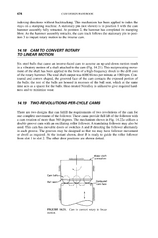
Six steel balls that cause an inverse-faced cam to assume an up-and-down motion result
in a vibratory motion of a shaft attached to the cam (Fig. 14.21). This reciprocating move-
ment of the shaft has been applied in the form of a high-frequency shock to the drill core
of the rotary hammer. The total shaft output was 6000 blows per minute at 1000rpm. Con-
toured and convex shaped, the grooved face of the cam contacts the exposed portion of
the balls; the rest of the balls are housed in recesses of the ball seat, which at the same
time acts as a spacer for the balls. Heat-treated Nitralloy is utilized to give required hard-
ness and to minimize wear.
14.19 TWO-REVOLUTIONS-PER-CYCLE CAMS
There are two designs that can fulfill the requirements of two revolutions of the cam for
one complete movement of the follower. These cams provide full lift of the follower with
a cam rotation of more than 360 degrees. The mechanism shown in Fig. 14.22a utilizes a
double-groove cam with an oscillating roller follower. A translating follower may also be
used. This cam has movable doors or switches A and B directing the follower alternately
in each groove. The grooves may be designed so that we may have follower movement
or dwell as required. At the instant shown, door B is ready to guide the roller follower
from slot 1 to slot 2. The other door positions are shown dotted.
FIGURE 14.21. Cam to convert rotary to linear
motion.