
Page 484 - Cam Design Handbook
P. 484
THB14 9/19/03 7:58 PM Page 472
472 CAM DESIGN HANDBOOK
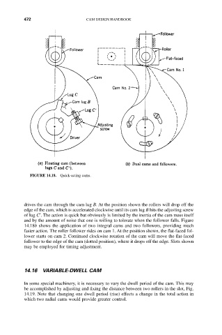
FIGURE 14.18. Quick-acting cams.
drives the cam through the cam lug B. At the position shown the rollers will drop off the
edge of the cam, which is accelerated clockwise until its cam lug B hits the adjusting screw
of lug C¢. The action is quick but obviously is limited by the inertia of the cam mass itself
and by the amount of noise that one is willing to tolerate when the follower falls. Figure
14.18b shows the application of two integral cams and two followers, providing much
faster action. The roller follower rides on cam 1. At the position shown, the flat-faced fol-
lower starts on cam 2. Continued clockwise rotation of the cam will move the flat-faced
follower to the edge of the cam (dotted position), where it drops off the edge. Slots shown
may be employed for timing adjustment.
14.16 VARIABLE-DWELL CAM
In some special machinery, it is necessary to vary the dwell period of the cam. This may
be accomplished by adjusting and fixing the distance between two rollers in the slot, Fig.
14.19. Note that changing one dwell period (rise) effects a change in the total action in
which two radial cams would provide greater control.