
Page 500 - Cam Design Handbook
P. 500
THB14 9/19/03 7:58 PM Page 488
488 CAM DESIGN HANDBOOK
14.26.5 Multiple Double-End Cam for Intermittent Motion
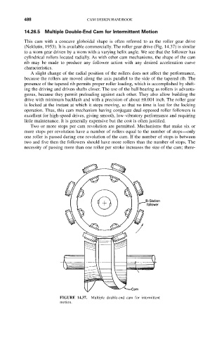
This cam with a concave globoidal shape is often referred to as the roller gear drive
(Neklutin, 1953). It is available commercially. The roller gear drive (Fig. 14.37) is similar
to a worn gear driven by a worn with a varying helix angle. We see that the follower has
cylindrical rollers located radially. As with other cam mechanisms, the shape of the cam
rib may be made to produce any follower action with any desired acceleration curve
characteristics.
A slight change of the radial position of the rollers does not affect the performance,
because the rollers are moved along the axis parallel to the side of the tapered rib. The
presence of the tapered rib permits proper roller loading, which is accomplished by shift-
ing the driving and driven shafts closer. The use of the ball bearing as rollers is advanta-
geous, because they permit preloading against each other. They also allow building the
drive with minimum backlash and with a precision of about ±0.001 inch. The roller gear
is locked at the instant at which it stops moving, so that no time is lost for the locking
operation. Thus, this cam mechanism having conjugate dual-opposed roller followers is
excellent for high-speed drives, giving smooth, low-vibratory performance and requiring
little maintenance. It is generally expensive but the cost is often justified.
Two or more stops per cam revolution are permitted. Mechanisms that make six or
more stops per revolution have a number of rollers equal to the number of stops—only
one roller is passed during one revolution of the cam. If the number of stops is between
two and five then the followers should have more rollers than the number of stops. The
necessity of passing more than one roller per stroke increases the size of the cam; there-
FIGURE 14.37. Multiple double-end cam for intermittent
motion.