
Page 503 - Cam Design Handbook
P. 503
THB14 9/19/03 7:58 PM Page 491
SPECIAL CAM MECHANISMS 491
5
3
Cam
3
6
4
3 1
2
FIGURE 14.39. Cam-modulated stamping machine (Erdman and Sandor, 1984).
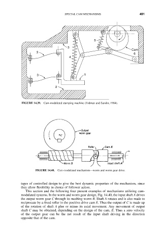
FIGURE 14.40. Cam-modulated mechanism—worm and worm gear drive.
tages of controlled design to give the best dynamic properties of the mechanism, since
they allow flexibility in choice of follower action.
This section and the following four present examples of mechanisms utilizing cam-
modulated systems. In the worm and worm gear design, Fig. 14.40, the input shaft A drives
the output worm gear C through its meshing worm B. Shaft A rotates and is also made to
reciprocate by a fixed roller in the positive-drive cam E. Thus the output of C is made up
of the rotation of shaft A plus or minus its axial movement. Any movement of output
shaft C may be obtained, depending on the design of the cam, E. Thus a zero velocity
of the output gear can be the net result of the input shaft driving in the direction
opposite that of the cam.