
Page 504 - Cam Design Handbook
P. 504
THB14 9/19/03 7:58 PM Page 492
492 CAM DESIGN HANDBOOK
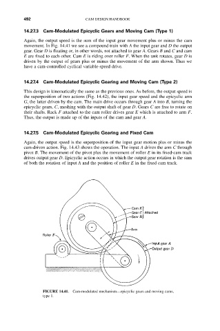
14.27.3 Cam-Modulated Epicyclic Gears and Moving Cam (Type 1)
Again, the output speed is the sum of the input gear movement plus or minus the cam
movement. In Fig. 14.41 we see a compound train with A the input gear and D the output
gear. Gear D is floating or, in other words, not attached to gear A. Gears B and C and cam
E are fixed to each other. Cam E is riding over roller F. When the unit rotates, gear D is
driven by the output of gears plus or minus the movement of the arm shown. Thus we
have a cam-controlled cyclical variable-speed drive.
14.27.4 Cam-Modulated Epicyclic Gearing and Moving Cam (Type 2)
This design is kinematically the same as the previous ones. As before, the output speed is
the superposition of two actions (Fig. 14.42), the input gear speed and the epicyclic arm
G, the latter driven by the cam. The main drive occurs through gear A into B, turning the
epicyclic gears, C, meshing with the output shaft of gear D. Gears C are free to rotate on
their shafts. Rack F attached to the cam roller drives gear E which is attached to arm F.
Thus, the output is made up of the inputs of the cam and gear A.
14.27.5 Cam-Modulated Epicyclic Gearing and Fixed Cam
Again, the output speed is the superposition of the input gear motion plus or minus the
cam-driven action. Fig. 14.43 shows the operation. The input A drives the arm C through
pivot B. The movement of the pivot plus the movement of roller E in its fixed-cam track
drives output gear D. Epicyclic action occurs in which the output gear rotation is the sum
of both the rotation of input A and the position of roller E in the fixed cam track.
FIGURE 14.41. Cam-modulated mechanism—epicyclic gears and moving cams,
type 1.