
Page 508 - Cam Design Handbook
P. 508
THB14 9/19/03 7:59 PM Page 496
496 CAM DESIGN HANDBOOK
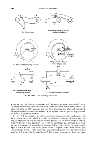
FIGURE 14.46. Cam computing mechanisms.
In this, we may call X the input parameter and Y the output parameter with the F(X) being
any single-valued continuous function with a derivative held within certain limits. The
latter restriction on F(X) prevents the cam from becoming too large and impractical.
Among the many functions that have been cut are squares, roots, reciprocals, trigonometric
functions, and empirical functions.
In Fig. 14.46 we indicate some of the possibilities of cam computer mechanisms with
the nonpositive drive types held in contact by springs (not shown). Of course, any cam
may be employed. In Fig. 14.46a we see the general case of two contours in contact,
usually with pure rolling action. In Fig. 14.46b we see input X as a constant-speed rotat-
ing cam and output Y as an oscillating follower. In Fig. 14.46c we have a spiral rotating
input X with a positive drive pin in groove output Y. Figure 14.46d, often called a gear
cam, is similar to Fig. 14.46c except that the output parameter Y is a rotating pin gear
meshing with grooves in the spiral input X. The primary advantage of these two spiral