Page 513 - Cam Design Handbook
P. 513
THB14  9/19/03  7:59 PM  Page 501

                                   SPECIAL CAM MECHANISMS                  501

            14.28.4 Basic Spiral Cam Constants

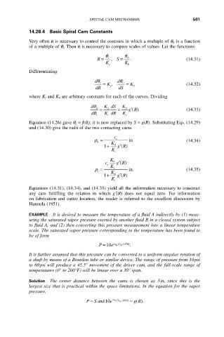
            Very often it is necessary to control the contours in which a multiple of q 0 is a function
            of a multiple of q i. Then it is necessary to compare scales of values. Let the functions
                                          q      q
                                      R =  i  ,  S =  0  .               (14.31)
                                          K      K
                                           i      0
            Differentiating
                                      dq  i  =  K ,  dq  0  =  K         (14.32)
                                      dR   i   dS   0
            where K i and K 0 are arbitrary constants for each of the curves. Dividing
                                    dq  0  =  K dS  =  K 0  gR           (14.33)
                                          0
                                                   ¢().
                                    dq   K dR   K
                                      i   i      i
            Equation (14.26) gave q o = f(q i); it is now replaced by S = g(R). Substituting Eqs. (14.29)
            and (14.30) give the radii of the two contacting cams
                                             c
                                     r =      e    in                    (14.34)
                                      0     K
                                         1+  0  gR
                                               ¢()
                                            K i
                                           K
                                               ¢()
                                         c e  0  gR
                                      r =   K i    in.                   (14.35)
                                       i    K
                                               ¢()
                                         1 +  0  gR
                                            K i
            Equations (14.31), (14.34), and (14.35) yield all the information necessary to construct
            any  cam  fulfilling  the  relation  in  which  g¢(R)  does  not  equal  zero.  For  information
            on fabrication and cutter location, the reader is referred to the excellent discussion by
            Hannula (1951).
            EXAMPLE It is desired to measure the temperature of a fluid A indirectly by (1) meas-
            uring the saturated vapor pressure exerted by another fluid B in a closed system subject
            to fluid A, and (2) then converting this pressure measurement into a linear temperature
            scale. The saturated vapor pressure corresponding to the temperature has been found to
            be of form
                                       P =10 e 6 t m ( t m +470  ) .

            It is further assumed that this pressure can be converted to a uniform angular rotation of
            a shaft by means of a Bourdon tube or similar device. The range of pressure from 10psi
            to 60psi will produce a 45.5° movement of the driver cam, and the full-scale range of
            temperatures (0° to 200°F) will be linear over a 30° span.

            Solution  The  center  distance  between  the  cams  is  chosen  as  3in,  since  this  is  the
            largest size that is practical within the space limitations. In the equation for the vapor
            pressure,
                                              (
                                  P = and 10 e  6 t m t +470  )  = ().
                                     S
                                                    g R
                                               m

