Page 509 - Cam Design Handbook
P. 509
THB14  9/19/03  7:59 PM  Page 497

                                   SPECIAL CAM MECHANISMS                  497

            cams is that more than one cam revolution is allowed, providing high accuracy. Spirals as
            high as eight revolutions have been used. Figure 14.46e shows a rotating cylindrical cam
            with input X and a translating output Y. Compared to a radial cam, cylindrical cams gen-
            erally have a smaller maximum dimension for a given follower travel. Figure 14.46f differs
            from all the others in that it is a 3-D cam or camoid, the mechanism having two degrees
            of freedom. The follower is often a spherical ball in contact with the cam profile. With the
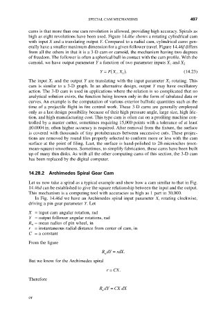
            camoid, we have output parameter Y a function of two parameter inputs X 1 and X 2
                                        Y = ( ,                          (14.23)
                                           F X X ).
                                              1  2
            The input X 1 and the output Y are translating with the input parameter X 2 rotating. This
            cam is similar to a 3-D graph. In an alternative design, output Y may have oscillatory
            action. The 3-D cam is used in applications where the relation is so complicated that no
            analytical solution exists, the function being known only in the form of tabulated data or
            curves. An example is the computation of various exterior ballistic quantities such as the
            time of a projectile flight in fire control work. These 3-D cams are generally employed
            only as a last design possibility because of their high pressure angle, large size, high fric-
            tion, and high manufacturing cost. This type cam is often cut on a profiling machine con-
            trolled by a master cutter, sometimes requiring 15,000 points with a tolerance of at least
            ±0.0004in; often higher accuracy is required. After removal from the fixture, the surface
            is covered with thousands of tiny protuberances between successive cuts. These projec-
            tions are removed by round files properly selected to conform more or less with the cam
            surface at the point of filing. Last, the surface is hand-polished to 20-micoinches (root-
            mean-square) smoothness. Sometimes, to simplify fabrication, these cams have been built
            up of many thin disks. As with all the other computing cams of this section, the 3-D cam
            has been replaced by the digital computer.


            14.28.2 Archimedes Spiral Gear Cam
            Let us now take a spiral as a typical example and show how a cam similar to that in Fig.
            14.46d can be established to give the square relationship between the input and the output.
            This mechanism is a computing tool with accuracies as high as 1 part in 30,000.
               In Fig. 14.46d we have an Archimedes spiral input parameter X, rotating clockwise,
            driving a pin gear parameter Y. Let
            X = input cam angular rotation, rad
            Y = output follower angular rotations, rad
            R w = mean radius of pin wheel, in
            r = instantaneous radial distance from center of cam, in
            C = a constant

            From the figure
                                         R dY =  rdX.
                                          w
            But we know for the Archimedes spiral
                                           r =  CX.

            Therefore
                                        RdY =  CX dX
                                         w
            or

